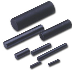
Rod Core / Antenna Cores
 |
|
|
|
|
|
|
|
|
|
|
|
|
|
|
 Features
:
Features
: |
|
Generally, Ferrite Rods are used as the core of solenoidal
Coils for two main functions: Tuning: moving the core
adjusts the coil to the required inductance value (L).
Advantages of the open circuit are high Q and a good temperature
stability. EMI suppression: the coil can carry a high
DC current without being saturated because of the open
magnetic circuit. In most cases, the frequency range will
not be limited by the material, but by the coil capacitance.
Curvature and mechanical tolerances of the standard range
ful fill the requirements international standard.The L
value and Q-factor are measured (up to 6 mm outer diameter)
in a standard coil. For solenoidal coils, open circuit,
No self shielding and not easy to saturate with DC. |
|
| |
|
|
Applications
: |
|
Tubes can be used in solenoid coils with almost the same
effect as Rods. The inner hole is often used to insert
wires to make a ferrite coil former. In EMI suppression
applications tubes can also be shifted over wires. Because
the magnetic flux path is then closed, a steep increase
in impedance results. In such cases howerver the sensitivity
for DC is rather high. Curvature and mechanical tolerances
of the standard range fulfill the requirements of DIN
41291. |
|
| |
|
|
|
|
|
Ordering
Code : |
|
|
|
|
|
|
|
Dimensions
(Rod Cores) : |
|
|
|
NO
|
ITEM
|
øA
|
D
|
Fig
|
|
1
|
R
0.76X4.83
|
0.76±0.05
|
4.82±0.25
|
|
|
2
|
R
1.65X8
|
|
8±0.3
|
|
|
3
|
R
1.65X14
|
|
14±0.6
|
|
|
4
|
R
1.7X6
|
1.7±0.1
|
6±0.3
|
|
|
5
|
R
1.75X18.8
|
1.75±0.1
|
18.5±0.6
|
|
|
6
|
R
1.9X10
|
1.9±0.1
|
10±0.3
|
|
|
7
|
R
2X14
|
2±0.1
|
14±0.5
|
|
|
8
|
R
2.3X20
|
2.3±0.1
|
20±0.6
|
|
|
9
|
R
2.5X20
|
2.5±0.1
|
20±0.6
|
|
|
10
|
R
2.8X11
|
2.8±0.1
|
11±0.3
|
|
|
11
|
R
3X11
|
3±0.1
|
10±0.3
|
|
|
12
|
R
3X20
|
3±0.1
|
20±0.6
|
|
|
13
|
R
3X36.5
|
3±0.1
|
36.5±1
|
|
|
14
|
R
3.3X20
|
3.3±0.1
|
20±0.6
|
|
|
15
|
R
3.5X25
|
3.5±0.15
|
25±0.8
|
|
|
16
|
R
4X10
|
4±0.15
|
10±0.3
|
|
|
17
|
R
4X20
|
4±0.1
|
20±0.5
|
|
|
18
|
R
4X30
|
4±0.15
|
30±0.8
|
|
|
|
NO
|
ITEM
|
øA
|
D
|
Fig
|
|
19
|
R
4.1X25
|
4.1±0.2
|
25±0.6
|
|
|
20
|
R
5X12.5
|
5±0.2
|
12.5±0.4
|
|
|
21
|
R
5X20
|
5±0.2
|
20±0.5
|
|
|
22
|
R
5X30
|
5±0.2
|
30±1
|
|
|
23
|
R
5.5X21
|
5.5±0.2
|
21±0.5
|
|
|
24
|
R
5.85X30
|
5.85±0.3
|
30±1
|
|
|
25
|
R
6X10
|
6.0±0.2
|
10±0.3
|
|
|
26
|
R
6X20
|
6.0±0.2
|
20±0.5
|
|
|
27
|
R
6X38
|
6.0±0.2
|
38±1
|
|
|
28
|
R
6.2X22.5
|
6.2±0.2
|
22.5±0.5
|
|
|
29
|
R
3.2X37.5
|
6.2±0.2
|
37.5±1
|
|
|
30
|
R
7.3X30
|
7.3±0.1
|
30±1
|
|
|
31
|
R
8X20
|
8±0.2
|
20±0.4
|
|
|
32
|
R
8X30
|
8±0.2
|
30±1
|
|
|
33
|
R
10X20
|
10±0.3
|
20±0.5
|
|
|
34
|
R
10X30
|
10±0.3
|
30±1
|
|
|
35
|
R
10X35
|
10±0.3
|
35±1
|
|
|
36
|
R
12X30
|
12±0.3
|
30±1
|
|
|
|
|
|
|
|
|
Dimensions
(Antenna Cores) : |
|
|
|
NO
|
ITEM
|
A
|
B
|
D
|
Fig
|
|
1
|
AR
10x50
|
100.3
|
903
|
|
|
|
2
|
AP
3x12x20
|
30.2
|
120.3
|
301.0
|
|
|
|
|
|
|
|
Shapes
: |
|
|
|
|
|